| |
How to
make a USB GPS Charging cable
GPS USB charging
cable for DConnex DC-230 and Seidio G2500
Jay Modha 30th August
2004DISCLAIMER - If
you damage your GPS Unit/PDA/PDA Mount/Car etc etc by doing
this don't blame me! |
| |
Like many of you, I’ve been looking
around for a good way to be able to use my PDA as a
navigational device in my car. The specific GPS device I got
was a DConnex DC-230 from eBay and since this was a
Bluetooth device it paired up nicely with my ipaq 4150 as it
also has Bluetooth support.
Now, most of the journeys I take are more than an hour so I
wanted the ability to charge my ipaq and my Bluetooth GPS
device at the same time. The GPS device that I have, is
charged via a USB cable; unfortunately I couldn’t find any
PDA mounts that supports charging a PDA and also a GPS
device via USB.
The closest thing I found was the Seidio G2500 which has the
ability to charge my PDA and also has a 5V DC output. So I
decided that I would make a cable that has the appropriate
connection to interface with the Seidio G2500 5V DC output
and the GPS unit.
I figured that I wouldn’t be the only one
who will run into this type of problem so here is a tutorial
of how I did this.
Now, I could’ve been lazy and got a splitter for my
cigarette lighter and powered both my PDA and GPS unit from
that, but I didn’t want a mass of cables in my car so I
decided to go for this more time consuming but nevertheless
cleaner way of charging both devices with the least amount
of cables.
|
Step 1 - Things you will need to
complete this project
| I sourced all of my stuff
from Maplin Electronics, but I’m sure you’ll find
similar products from your local electronics
retailer. Unfortunately I couldn’t find the correct
type of 4.0mm jack that could be wired straight into
the USB cable so I had to wire it into a 2.5mm line
socket and then connect a 2.5mm power plug into the
USB cable. |
|
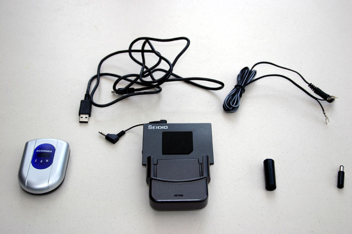
Fig 1.0 |
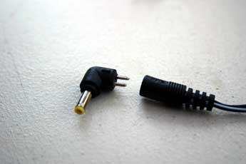
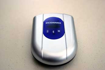
Figure 1.0 shows the items you
will need to complete this project. The items shown
(from left to right) are the DConnex Bluetooth GPS
receiver (with mini Type-B USB connecter), USB cable
(Type-B connector on one end and regular USB
connecter on the other end) Seidio G2500 PDA Mount,
Power adapter lead & 4.0mm DC connecter, 2.5mm line
socket and 2.5mm DC power plug.
Please keep in mind you will also need some wire
cutters, soldering iron and a multi meter
(optional). |
 |
 |
| Fig
1.1 |
Fig 1.2 |
 |
 |
| Fig 1.3 |
Fig 1.4 |
|
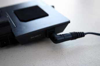
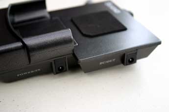
Figure 1.1 shows a close up of the Seidio
G2500's power connecters, (from left to right) the
first power connecter is used to charge the PDA and
also supply the voltage for the DC/OUT connection.
The DC/OUT connection is where our new cable will be
plugged in to charge the GPS unit.
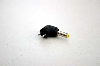
Figure 1.2 shows the DC connector that you will
need to plug into the Seidio G2500's DC/OUT
connection. You will use
this connector along with its matching power adapter
lead (Fig 1.3) to connect with 2.5mm line socket.
Figure 1.4 shows a close up of the GPS receiver. |
 |
 |
| Fig 1.5 |
Fig 1.6 |
 |
 |
| Fig 1.7 |
Fig 1.8 |
|
|
|
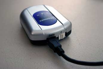
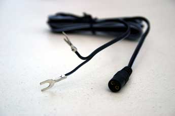
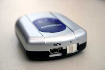
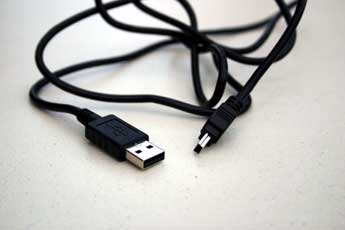
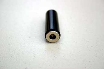
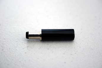
Figure 1.5 shows the rear of the GPS receiver,
the port labeled "DATA" is where the USB cable shown
in figure 1.6 will be plugged in.
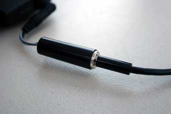
Figure 1.7 shows the 2.5mm line socket, the power
adapter lead show in in figure 1.3 will be wired
into this socket.
Figure 1.8 shows the 2.5mm DC connecter, this will
be wired with the USB cable shown in figure 1.6 (the
larger USB connecter will be cut off in place of
this connecter) which in turn, will be plugged into
the 2.5mm line socket shown in figure 1.7. |
|
Step 2 - Connecting the power
adapter lead to the 2.5mm line socket
Depending on where you place the GPS unit in
your car, you might want to trim the power adapter
lead so that there is not so much slack. I opted to
do this, because the USB cable was going to be long enough to allow me to place the GPS
receiver wherever I wanted. You will notice that the
power adapter cable actually consists of two cables,
one which is solid black, and another which is white
and black. For the purpose of this tutorial, the
white and black wire will be negative and the black
wire will be positive.
When you unscrew the 2.5mm line socket, you will
notice that it has two connections where the wires
from the power adapter lead will be soldered onto.
The connecter that is on the outside of the 2.5mm
socket is for the negative wire and the connecter
that is in the inside of the socket is for the
positive wire.
After you have soldered the wires onto the 2.5mm
line socket, you should have something that
resembles figure 2.0 below.
IMPORTANT: Please make sure to insert into the power
adapter lead the outer casing of the 2.5mm line
socket otherwise you will not be able to put it back
on once the wires have been soldered. |
|
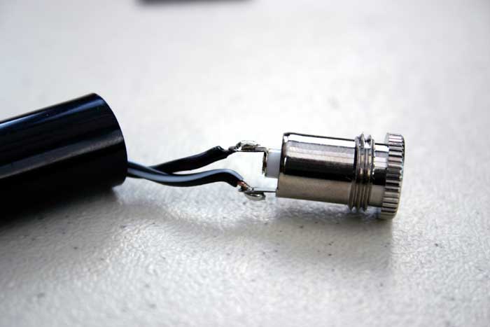
Fig 2.0 |
|
|
|
Step 3 - Connecting the 2.5mm DC
power plug to the USB cable
| Unscrew the 2.5mm power plug and you will notice
that like the 2.5mm line socket, this also has two
connections to where the USB wire will be soldered
onto. The same principle applies here, the inside
connection is for the positive wire and the outside
is for the negative. Figure 3.0 shows the
connections for the 2.5mm DC power plug. |
|
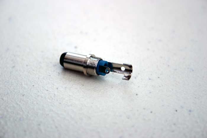
Fig 3.0 |
|
|
| The USB cable shown in figure 1.6 will need to
have the regular sized USB connector removed. This
can be done with a wire cutter. Once this is done,
you will need to strip the outer cabling to expose
the wires inside. Figure 3.1 shows what you should
see when this is done. |
|
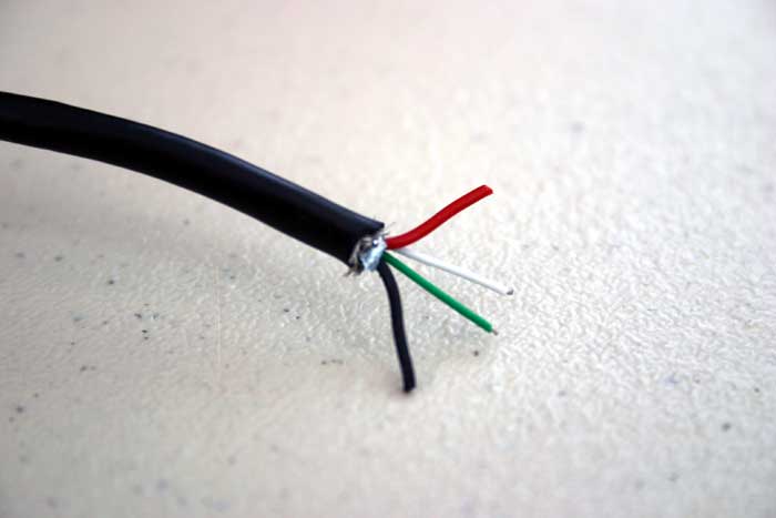
Fig 3.1 |
|
|
You might find there is some shielding around
the wires, this can be removed to expose the four
wires inside the cable. The two wires which we are
concerned with are the red and black ones. The white
and green wires can be trimmed down so that they do
not get in the way. Once this is done, simply solder
the red wire to the positive connecter of the 2.5mm
plug and the black wire to the negative connecter.
Figure 3.2 shows what you should be left with once
you have soldered the wires.
IMPORTANT: Please make sure to insert into the USB
cable the outer casing of the 2.5mm plug otherwise
you will not be able to put it back on once the
wires have been soldered. |
|
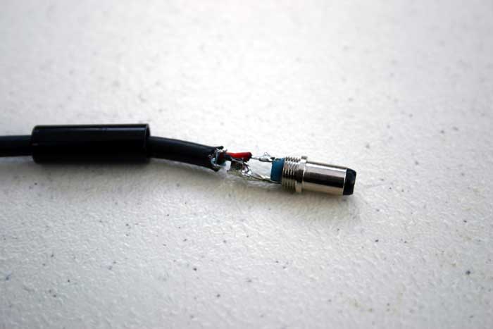
Fig 3.2 |
|
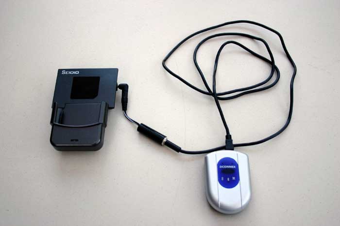
Step 4 - Connecting
it all together!
|
Conclusion
With everything connected together you should hopefully
have a fully working USB cable that will charge your GPS
unit (Or any other type of USB device) from the PDA mount.
It's always safe to check that the voltage output does not
exceed +/- 5V DC by using a multi meter.
I hope you found this tutorial helpful, let me know how your
installation goes or if you have any recommendations to
improving this. You can contact me via email
jmodha@3ill.co.uk |
| |
|